Building a OneWheel Clone
The Idea
I’m a college student, which opens the door to 3 issues: I have to cover reasonably large distances in small amounts of time, I’m extremely lazy, and I dont have the $2200 to spend on a OneWheel (Like what thats absurd). So, being the reasonable individual I am, decided that instead of looking into alternatives (like idk a bike), I would design and build my own OneWheel clone. I have certainly drawn inspiration from the original, using it for basic reference items like overall dimensions and tire information, but have designed my own structure, electronics system, and powertrain.
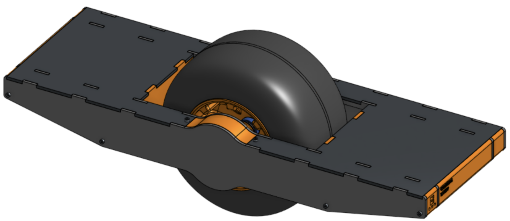
The structure
Most of this project will be built using an Ender 3 Pro 3d printer. This allows me to rapidly prototype by physically holding the component and feeling if it will work or not, and allows me to build shapes that I would otherwise have no ability to manufacture. Obviously as strong as 3d prints are, they will not be able to hold my weight under the stresses of navigating and bouncing around, so the actual structure will be supplied by 4 parallel layers on 3/16 6062 Aluminum frames. These will (hopefully) provide the strength and stability needed hold me and to support the entire machine. The 3d printed parts will provide some bracing and support, but are mostly cosmetic, as I simply don’t trust the plastic.
The control layer
The computing will occur on-device with an Arduino Uno and a pitch-aware accelerometer running a PID loop. The motor (Hopefully a GoBilda 5203 motor @ 312RPM) will be driven by a GoBilda motor driver (the cheapest I could find) via PWM. There will be a hardwired safety switch that will have to be pressed in order for the board to run, and the motor will automatically cut off if a tilt of over 17 degrees (z) and 10 degrees (x) is detected. The power system will run off a 12v 2.6 Ah SLA battery (Grainger 5EFF9).
The powertrain
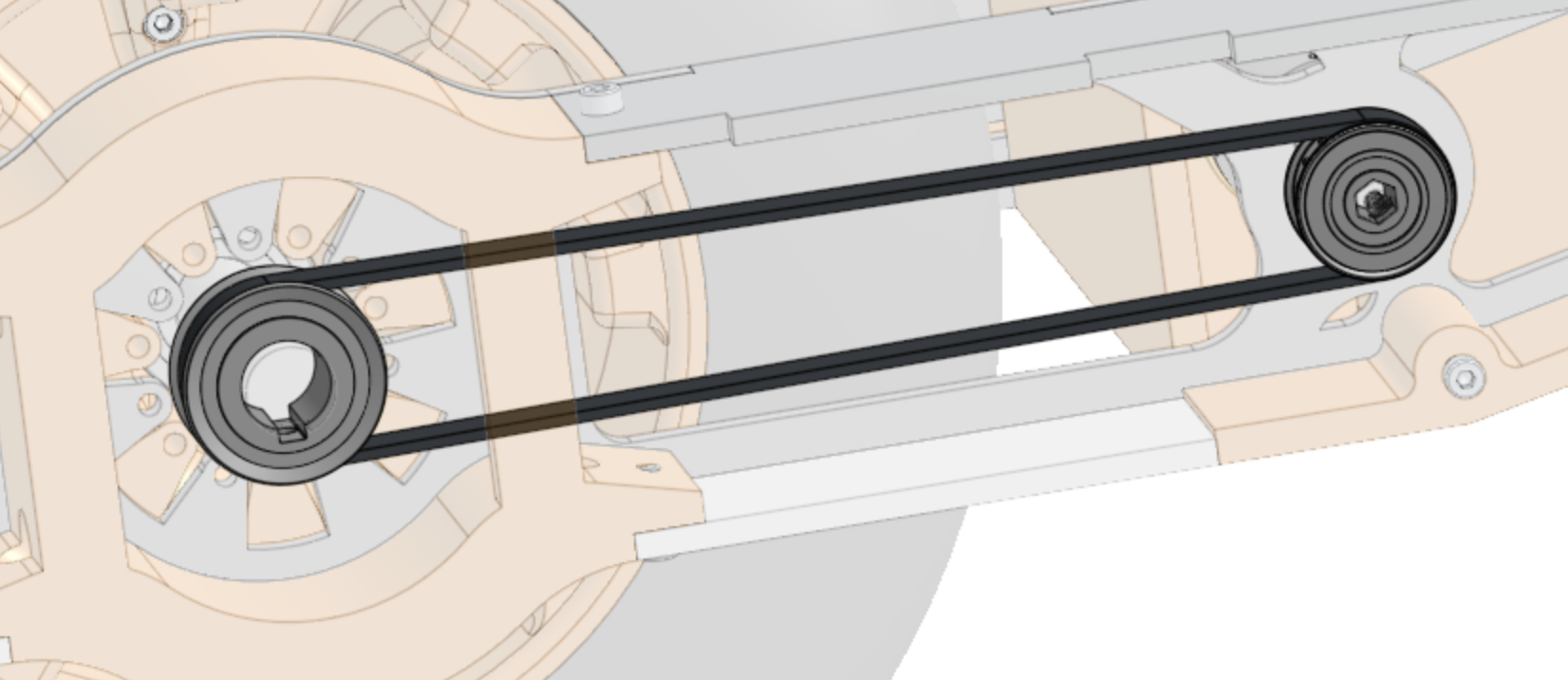
The motor and wheel are linked via a 95 tooth, 5mm pitch belt, connected to a GoBilda pulley attached to the motor and to a misumi pulley on the other. As terrible as mixing vendors tends to be on the design side, this was done to convert from the 8mm REX shaft on the motor to the 5/8” keyshaft (Grainger 30F575).
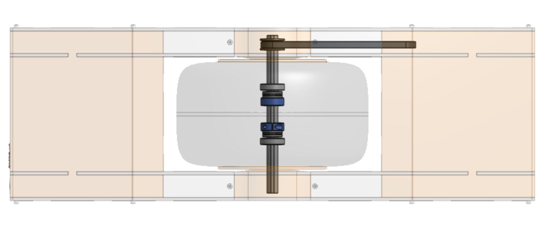
The delivery from the pulley to the actual wheel is slightly more complex because of the multitude of forces that can potentially be applied to the shaft. The shaft is supported by ball bearings both in the longitudinal and lattitudal direction, and is connected to the metal frame via the pillow components (3d printed; will have to be insanely sturdy) (not pictured).
The components
Outer structural frame
These relatively simple components serve as the outside-facing frame as well as part of the structure system.
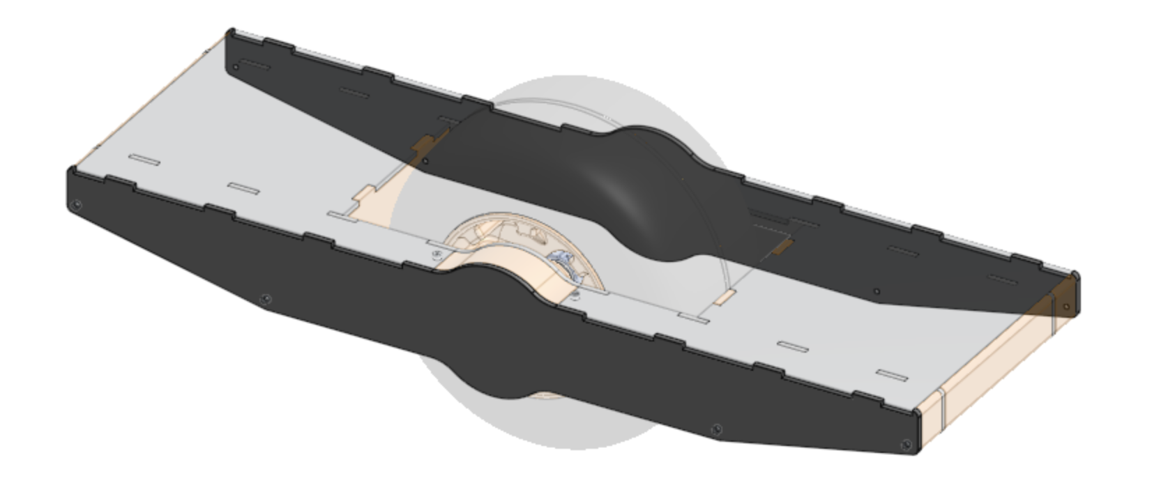
Sled system
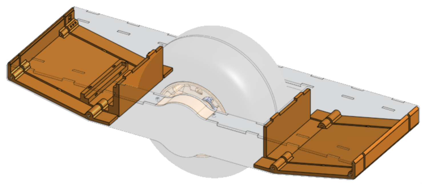
While the longitudinal support is mostly provided by the structural frames, the latitudinal support (z axix) is provided mostly by the boot boards and by 2 3d printed sleds. The sleds are both cosmetic and structural, and provide mounting points for the electronics and the battery. These parts took the most care to design as I was hoping to fit within the sizing volume of my Ender 3 Pro (which I did, barely). I ran a test print of the more elaborate sled (the one responsible for bolding the battery) and it came out less than perfect. I am satisfied with my design, but the print settings required some tuning. These prints take about 30 hours and about 800g of filament, so I am trying to print as few prototypes as possible.
The first prototype highlighted a few issues with my slicer configuration, mostly accuracy and fillament pull issues that had not shown themselves on much smaller prints:
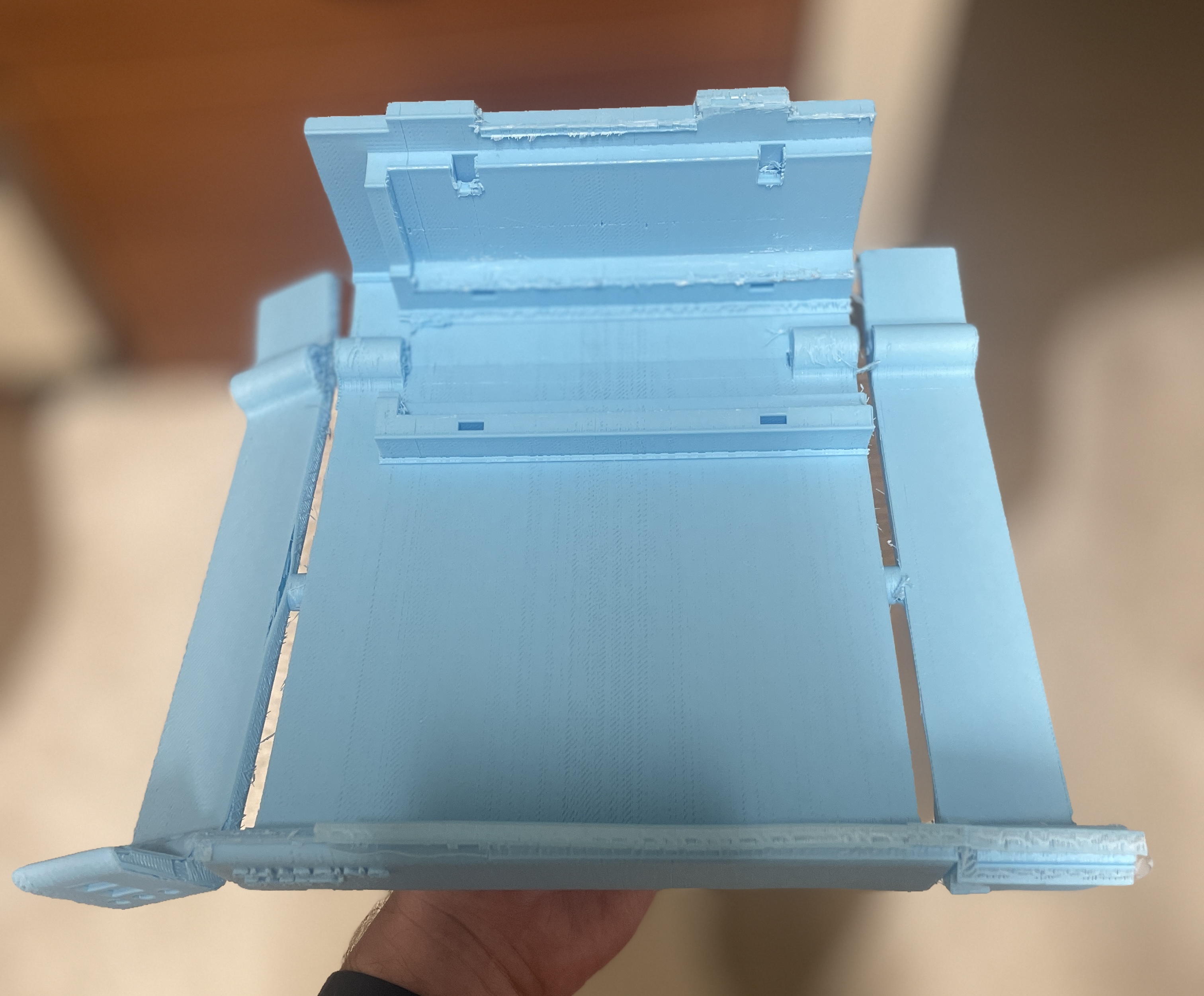
You can see a few issues in this print, most notably that the panel on the left is literally hanging on by a thread. This is because the layer height was set too high, and the print only had 3 outer perimeters. I have found that (even though it is most likely overkill) 6 perimeter layers provides an excellent amount of rigidity and puncture resistance. I also had my support material misconfigured on this print, there were way more supports than necessary, and I was not able to get many of them off cleanly, which resulted in the rough edges you can see (especially on the front edge). I have since fixed these issues and smaller prints are coming out much cleaner.
Pillow components
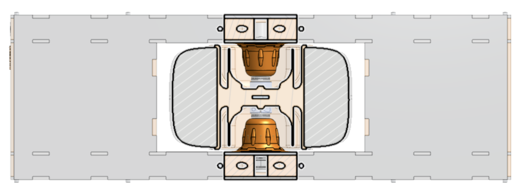
The pillows are used as a way to stabilize the driveshaft and to laterally hold the wheel in place. They are mostly just fancy spacers.
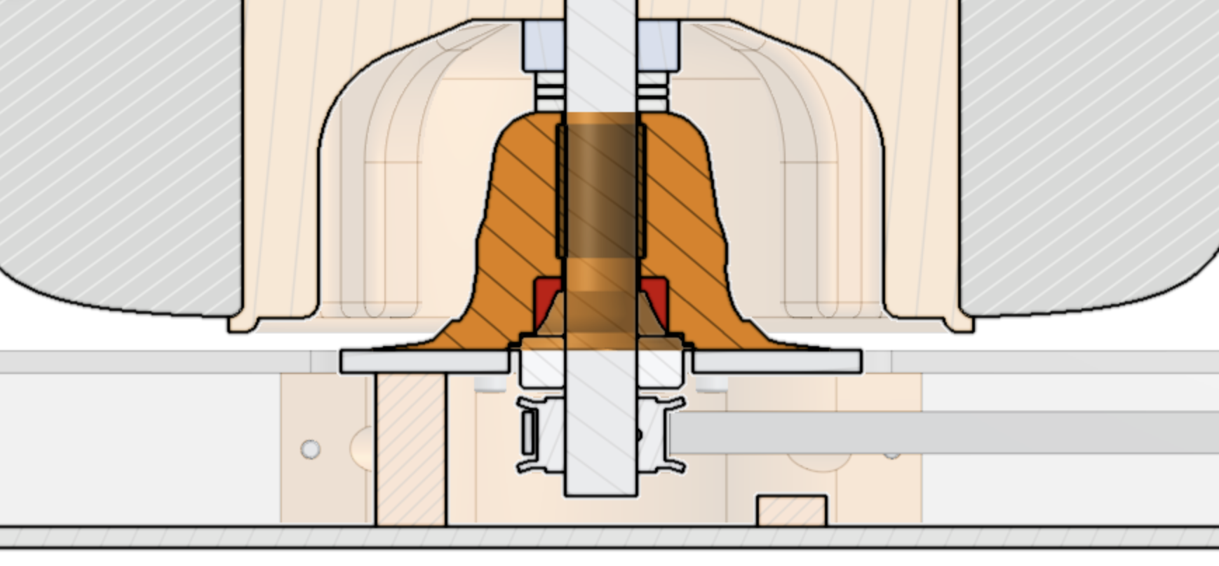
As you can see in the cutaway, most of the volume of the pillow is just solid print, but there is a metal insert that will hold the shaft. This is mostly to reduce wear on the 3d print as the shaft spins. My prototyping for this particularly unremarkable part has taken by far the most time and effort. Working with an unfamiliar printer where I don’t have a feel for it’s accuracy led to several parts being too tight or too loose to house the insert: (this should be perfectly flush with the edge)
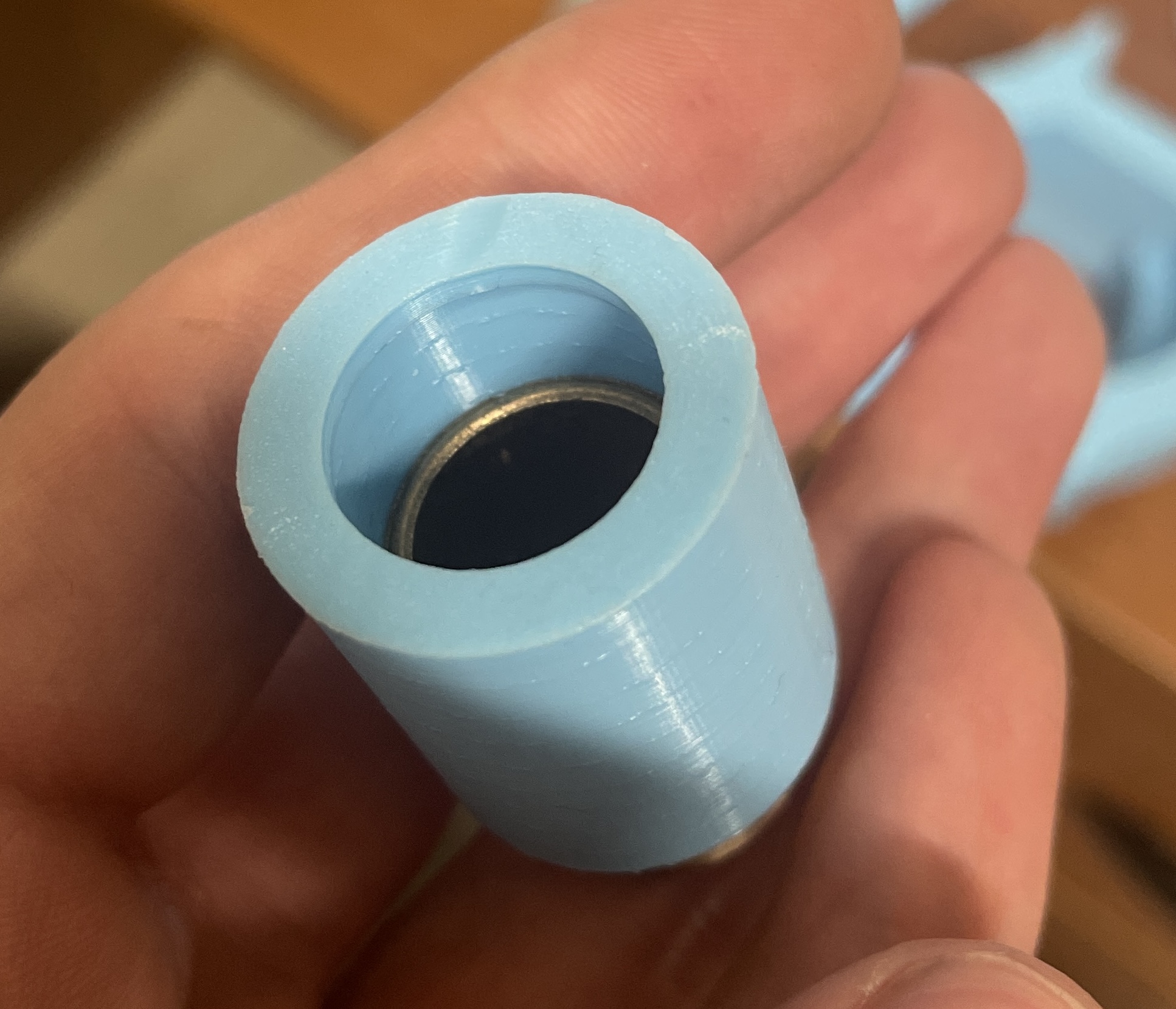
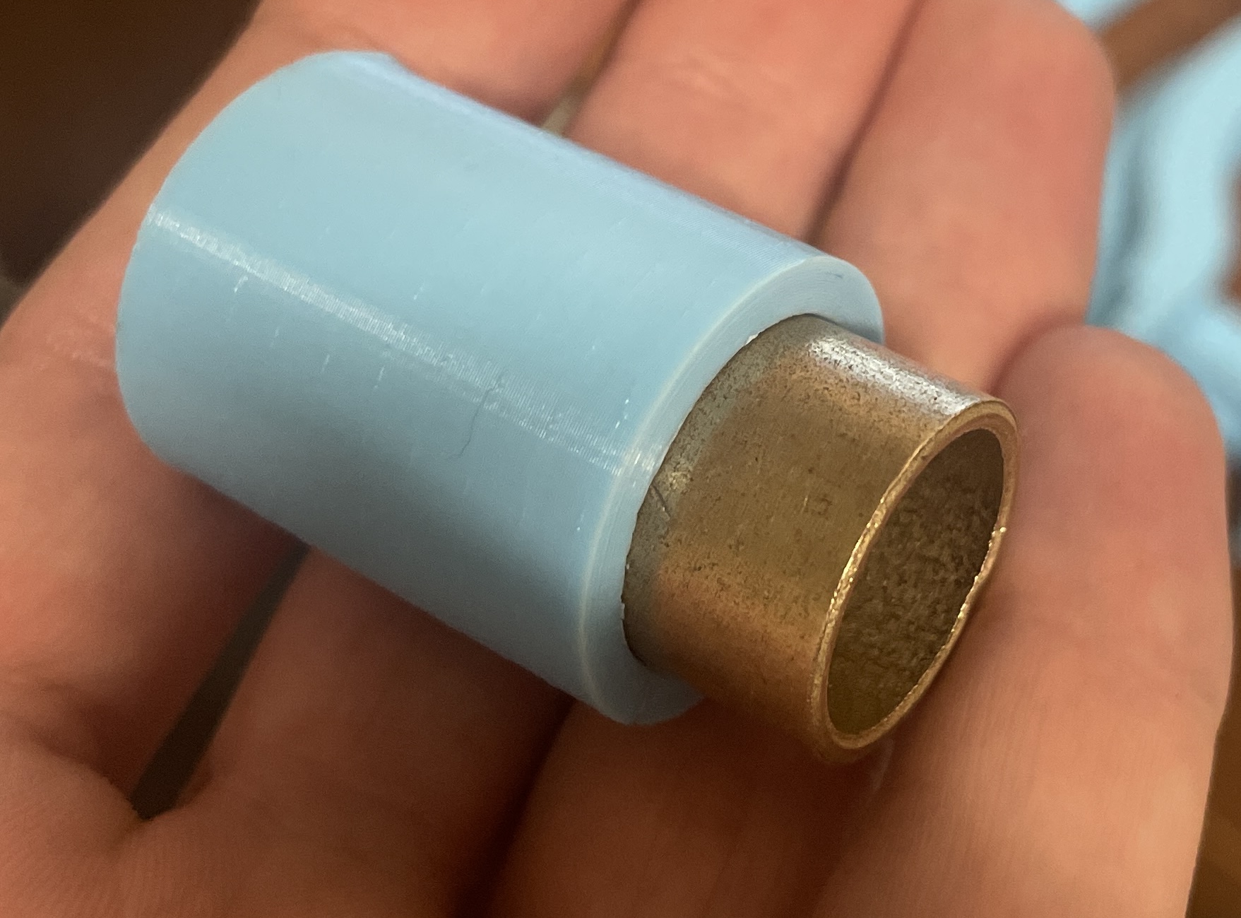
I did not run off a full prototype of the proper ID, but did eventaully discover the correct inner diameter to fit the bearing insert.
The bearing insert will be inserted mid-print by passing a M601 command, allowing me to insert the bearing, then it being held in place by the print. This is one of the really cool capabilities of a 3d printer, because embedding a part in another solid component would otherwise be impossible.
